A JUKI custom gripper nozzle project makes more sense when it begins with the PCB and the component rather than with the tooling itself. This case involves a power supply board with magnetic components, capacitors, heat sinks, transformers, and parts that are more structurally complex than conventional chip components.
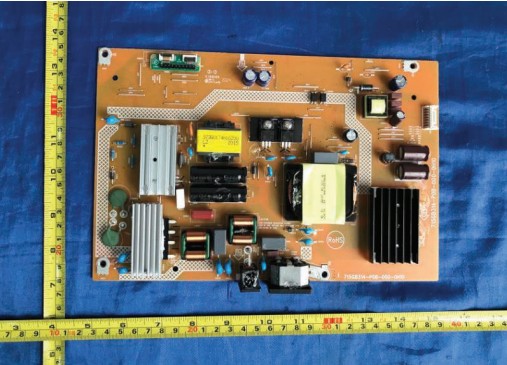
One of the parts in the handling study is a line choke. Its copper windings, exposed leads, and irregular external geometry make automated pickup more challenging than its size suggests.
Step 1 Understand the Component in Three Dimensions

A single top-view photo is not enough for custom tooling. The bottom reveals the lead structure, while side views show winding height and available contact zones. Key observations included the uneven coil surface, structural gaps, exposed leads, and limited continuous flat area for vacuum contact.
Step 2 Compare the Pickup Principle With the Component
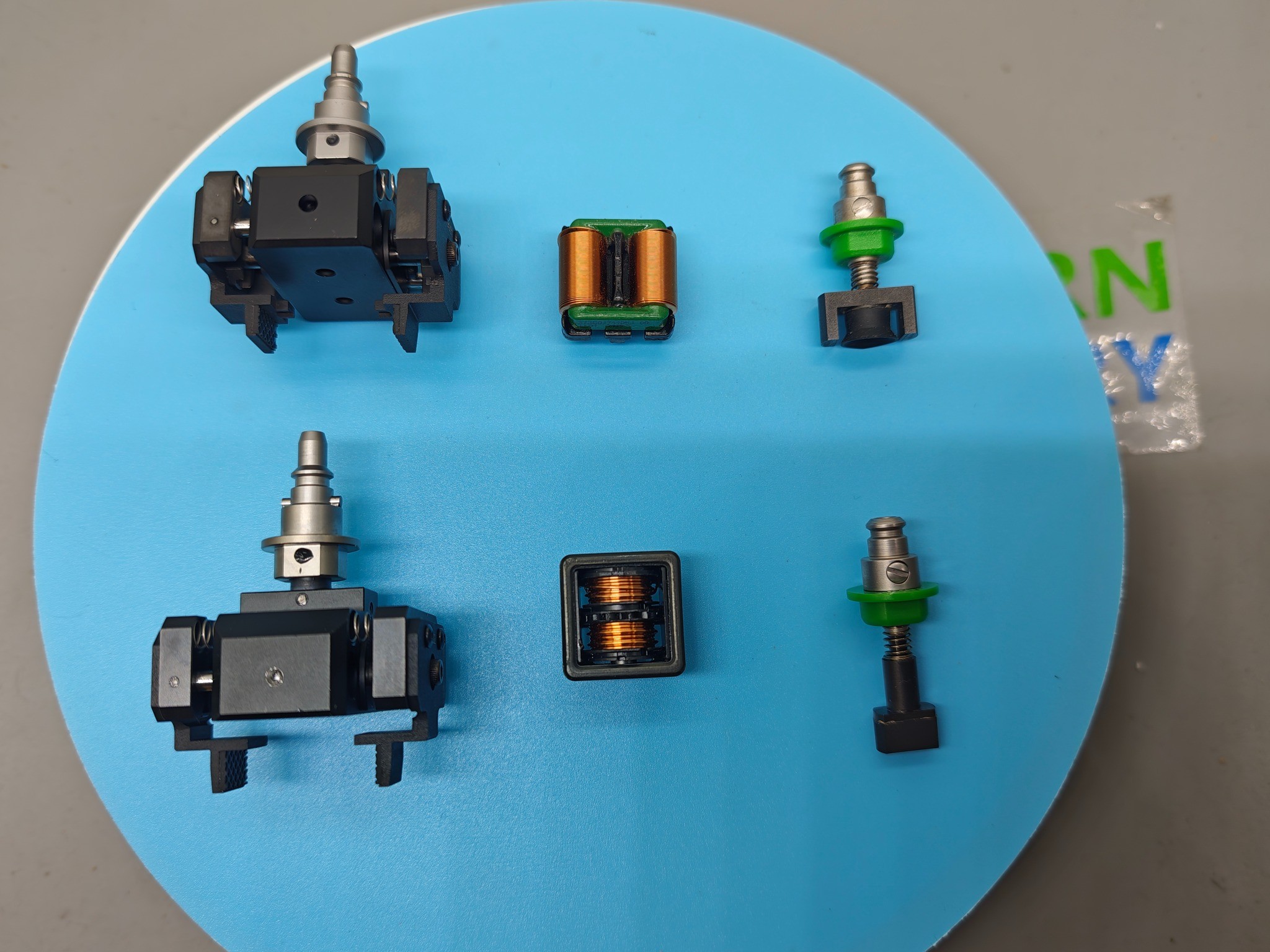
Vacuum pickup depends on a suitable contact area and air seal; a mechanical gripper can control the component from selected side features. For this JUKI application, the selected concept was a pneumatic clamp-type nozzle with opposing jaws.
Step 3 Build Both Interfaces

A custom gripper has two interfaces that must be engineered together:
- Component side: size, weight, lead position, gripping area, center of mass, and sensitive surfaces.
- Machine side: nozzle interface, actuation, installation geometry, clearance, orientation, and tool-changing requirements.
- Process: pickup height, feeding method, placement orientation, movement profile, and required repeatability.
Pneumatic energy controls jaw opening and closing. The engineering work lies in matching jaw motion, contact position, and interface to the actual component and machine.
Step 4 Check Opening Range and Clearance

The jaw opening must provide enough clearance to approach without touching leads or adjacent structures. The gripping stroke must establish repeatable contact without excessive force. This engineering photograph documents how the physical part and tool were evaluated together.
Step 5 Run a Simulated Pickup Test

The simulated test checks the core mechanical concept: approach, grip, lift, hold during movement, and release. It supports a specific conclusion—the prototype can mechanically grip, lift, and hold the target component under the demonstrated conditions. It does not by itself prove full production performance.
What Production-Line Validation Should Check Next
- Pickup repeatability and consistent component entry into the jaws.
- Holding stability during acceleration, XY movement, and rotation.
- Reliable component position and orientation recognition.
- Accurate placement and release.
- Clearance around feeders, fixtures, nearby components, and machine hardware.
- Stability of jaws, springs, interfaces, and component surfaces over repeated cycles.
Keeping prototype feasibility and production validation separate makes the case study more credible and defines what still needs to be verified.
Why This Case Matters Beyond One Line Choke
Connectors, coils, transformers, relays, sensors, shielding parts, camera modules, and other odd-form devices can create similar handling questions. The solution may be a customized vacuum tip, soft-contact nozzle, multi-hole design, mechanical gripper, or a different feeding strategy. The correct choice depends on component geometry and the production process.
What We Need for a Similar JUKI Application
- Clear component photos from the top, bottom, and sides.
- A dimensional drawing or physical sample.
- Component length, width, height, and weight.
- JUKI machine model and placement-head information.
- Existing nozzle or machine-interface photos and part numbers.
- A description or video of the current pickup problem.
- Expected production conditions and validation requirements.
FAQ About JUKI Custom Gripper Nozzles
Is this an OEM JUKI nozzle?
The tooling shown is a customized compatible solution for a JUKI application. It should not be described as an OEM JUKI product unless its origin is specifically verified.
Can the same gripper be used for other components?
Possibly, if component dimensions and safe gripping regions are sufficiently similar. Jaw geometry or opening range often needs adjustment for each part family.
What comes after the simulated pickup test?
Install the tooling on the intended machine and validate pickup, movement, recognition, placement, release, clearance, and repeated-cycle behavior.
Have a Similar Component-Handling Challenge?
Send us the component sample or photos, drawing and dimensions, machine model and head, existing interface details, and a pickup-problem video if available.
Trademark note: JUKI is a trademark of its respective owner. References describe machine compatibility and application context and do not imply OEM manufacture or endorsement unless explicitly stated.