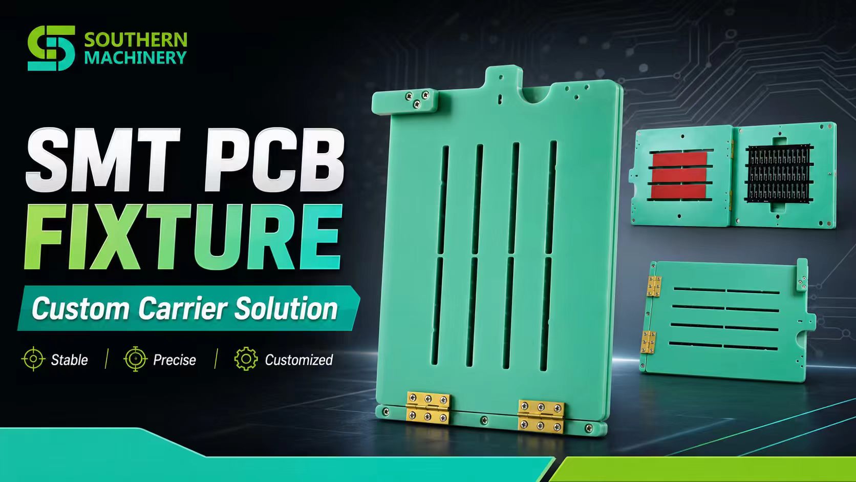
A custom SMT PCB fixture is production tooling designed around a specific PCB or panel. It locates the board, supports it at controlled areas and keeps machine access clear. The same basic idea can serve router depaneling, PCBA assembly, manual insertion, inspection, testing, handling and automation—but the fixture geometry must match the process.
What Is a Custom SMT PCB Fixture Used For?
The short answer: it gives a PCB a repeatable mechanical reference while protecting the board and exposing only the areas required by the operation.
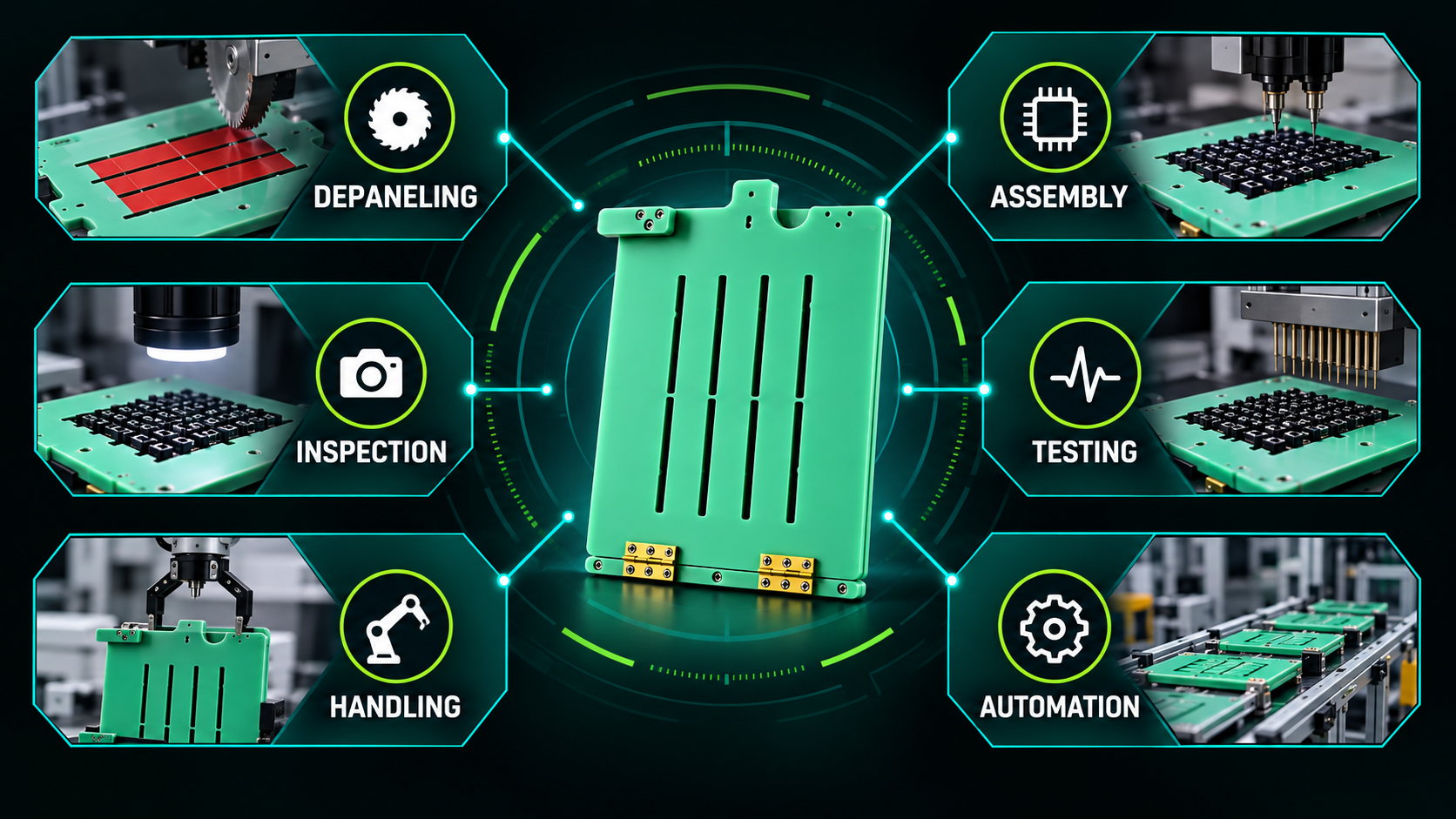
| Application | Main fixture requirement |
|---|---|
| Router depaneling | Rigid support plus an unobstructed cutting path |
| PCBA assembly | Accurate positioning and component access |
| Manual insertion | Support against insertion force |
| Inspection | Repeatable presentation to a camera or operator |
| Testing or programming | Stable location and probe/connector access |
| PCB handling | Protection and controlled transport |
| Automation | Reliable datums for robots and machines |
1. PCB Router Depaneling
A router fixture holds a panel flat while the spindle separates individual boards. Support should be close enough to reduce vibration, but the cutter, dust extraction and tool path must remain clear. Locating pins, machined pockets and edge stops are defined from the actual panel data.
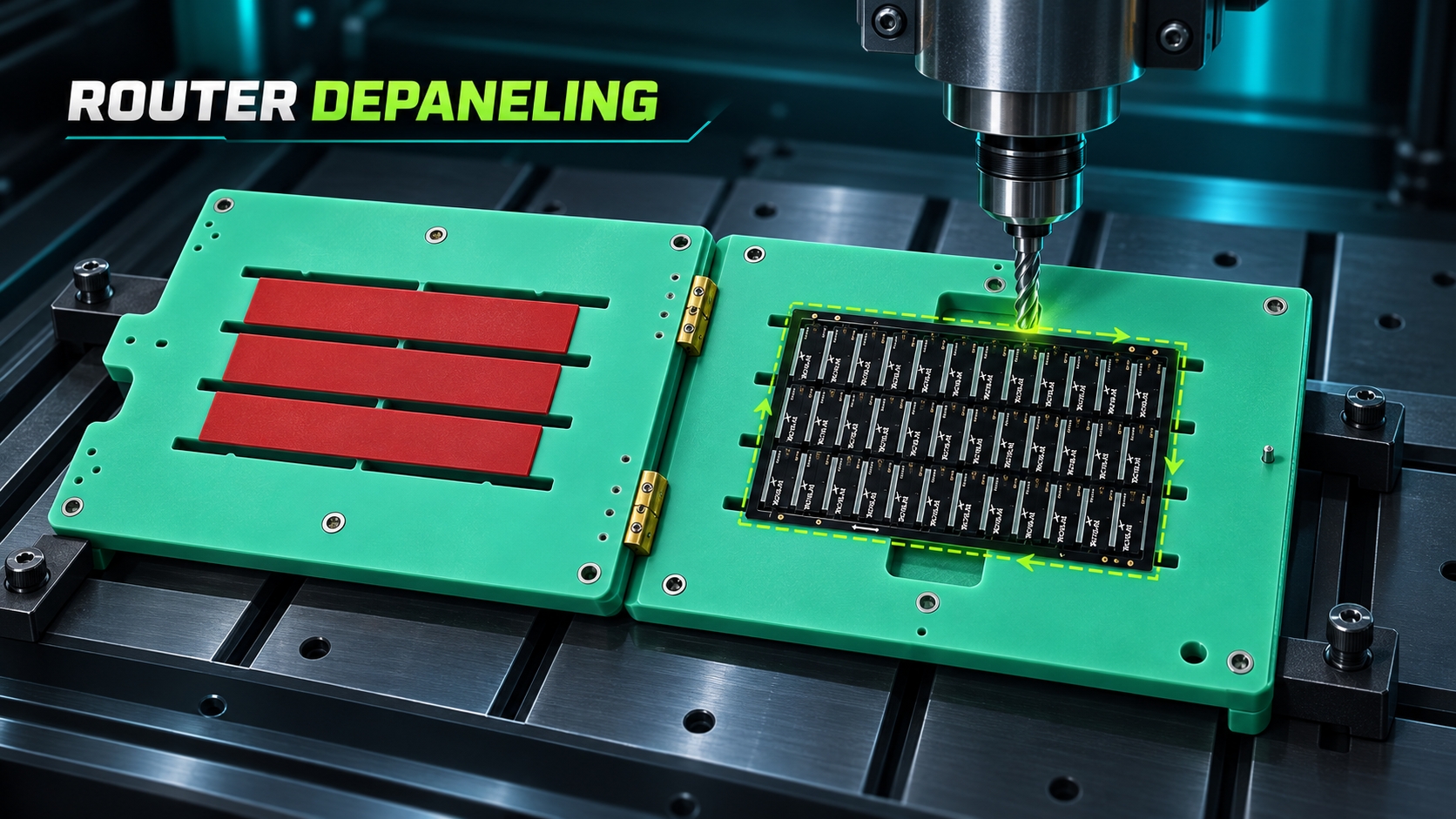
For this application, send the panel outline, tab or bridge locations, expected routing path, component-side photographs and router model. A generic holder rarely provides the same support-to-clearance balance.
2. PCBA Assembly and Manual Insertion
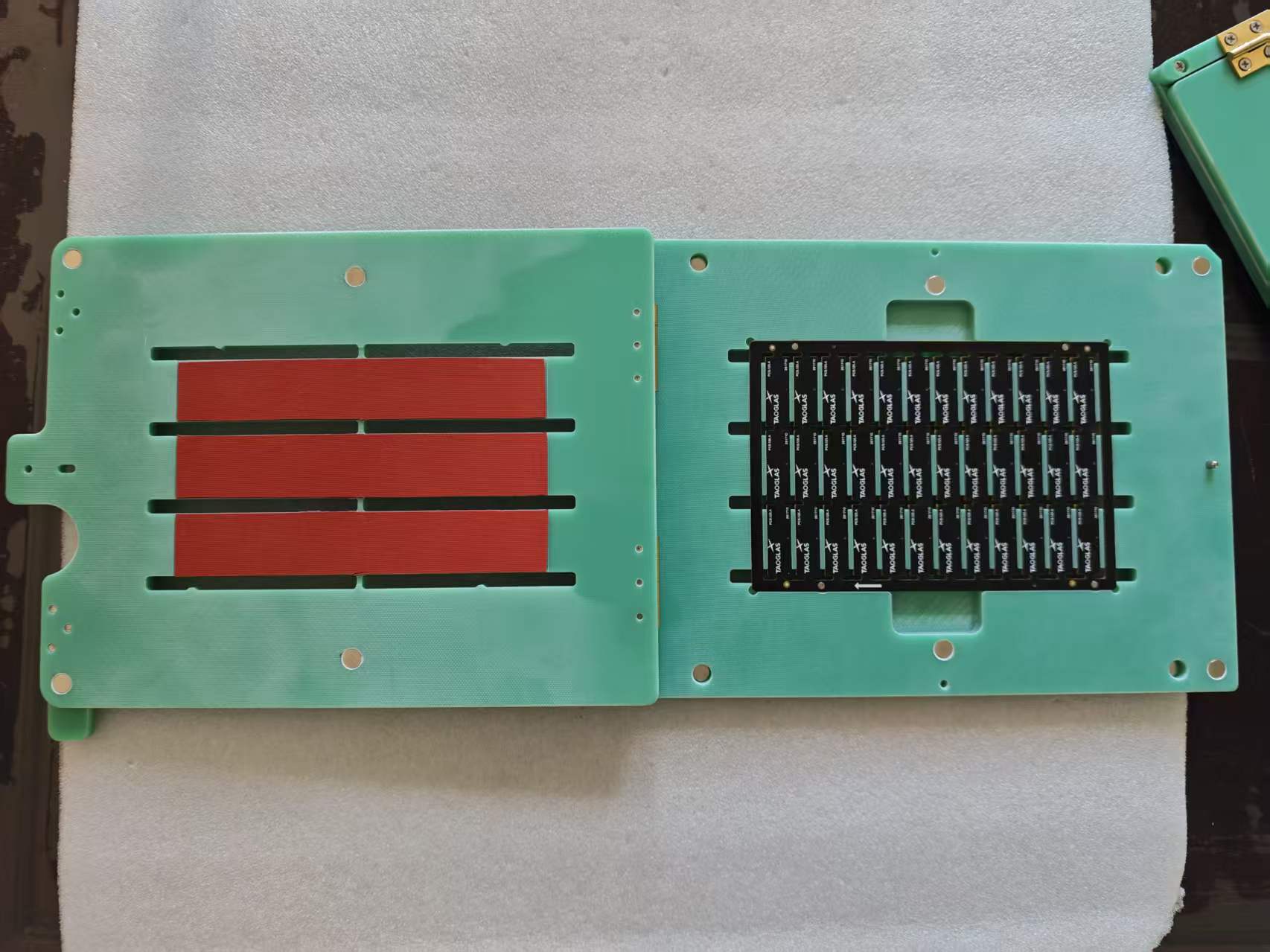
During assembly, the fixture keeps the PCB from shifting while an operator or machine places parts. For manual THT insertion, the base must resist insertion force without pressing against bottom-side components. Relief pockets and openings are therefore as important as the outside dimensions.
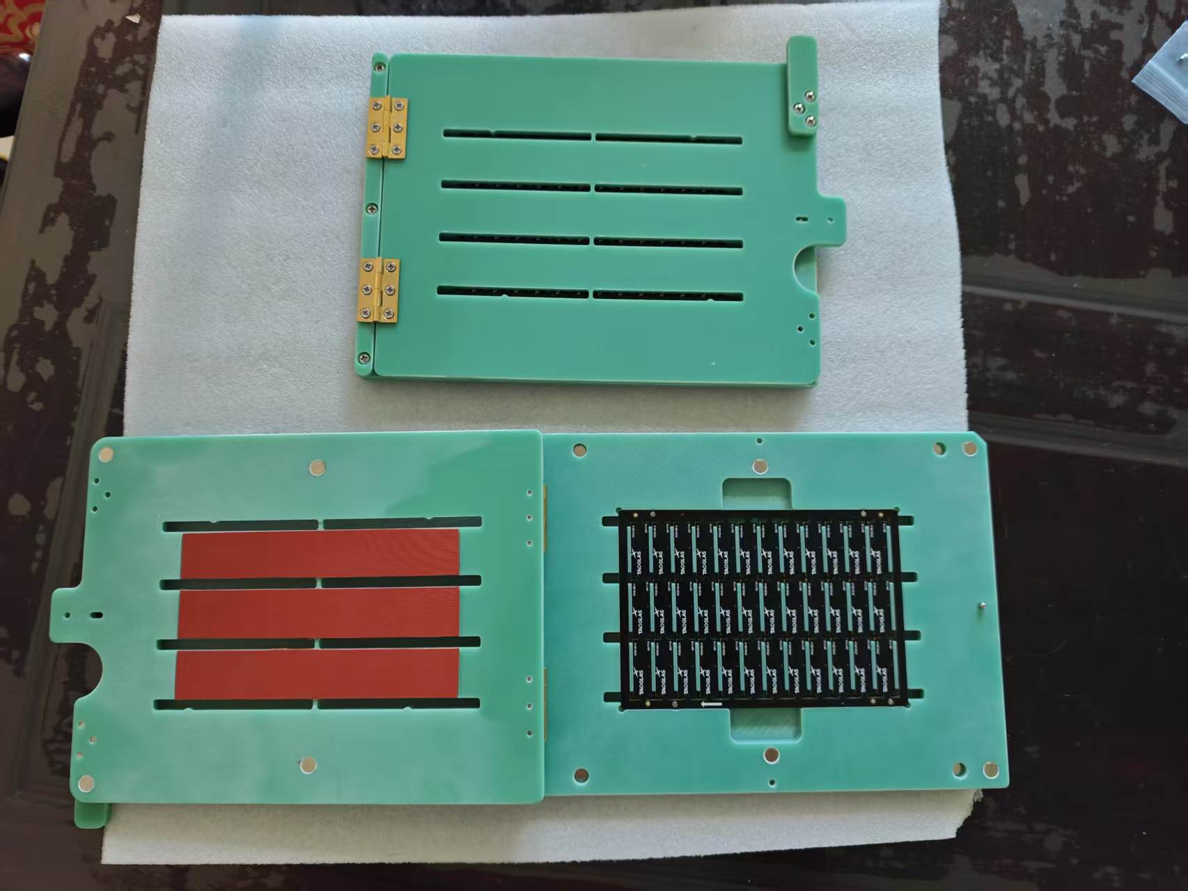
The photographed fixture uses a hinged construction: the PCB loads into the right-hand locating area while the opposite plate provides the designed relationship for the production step. This is a real manufactured tool, not a generic rendering.
3. PCB Positioning and Support
Repeatability comes from defined locating features. Depending on the board, these may include tooling holes, edge references, machined pockets, stops or removable blocks. The engineer must also decide where support is safe; a point placed under a component can cause damage or an unstable fit.
4. Inspection, Testing and Programming
An inspection fixture presents each board in the same position, helping a camera or operator compare the same regions consistently. A test or programming fixture adds access for probes, connectors or pogo-pin interfaces. In both cases, the PCB must be constrained without blocking the feature being inspected or contacted.
5. PCB Handling and Protection
A carrier can protect a thin, flexible or densely populated assembly during movement between operations. It also gives conveyors, loaders and operators a consistent outside shape to handle. This reduces direct contact with the PCB and makes orientation easier to control.
6. Automated Equipment Integration
Automation needs predictable datums. A custom carrier can provide external reference edges, locating holes, clamp zones and robot-access features that the bare PCB does not provide. Machine model, conveyor width, loading direction and sensor positions should be shared before design begins.
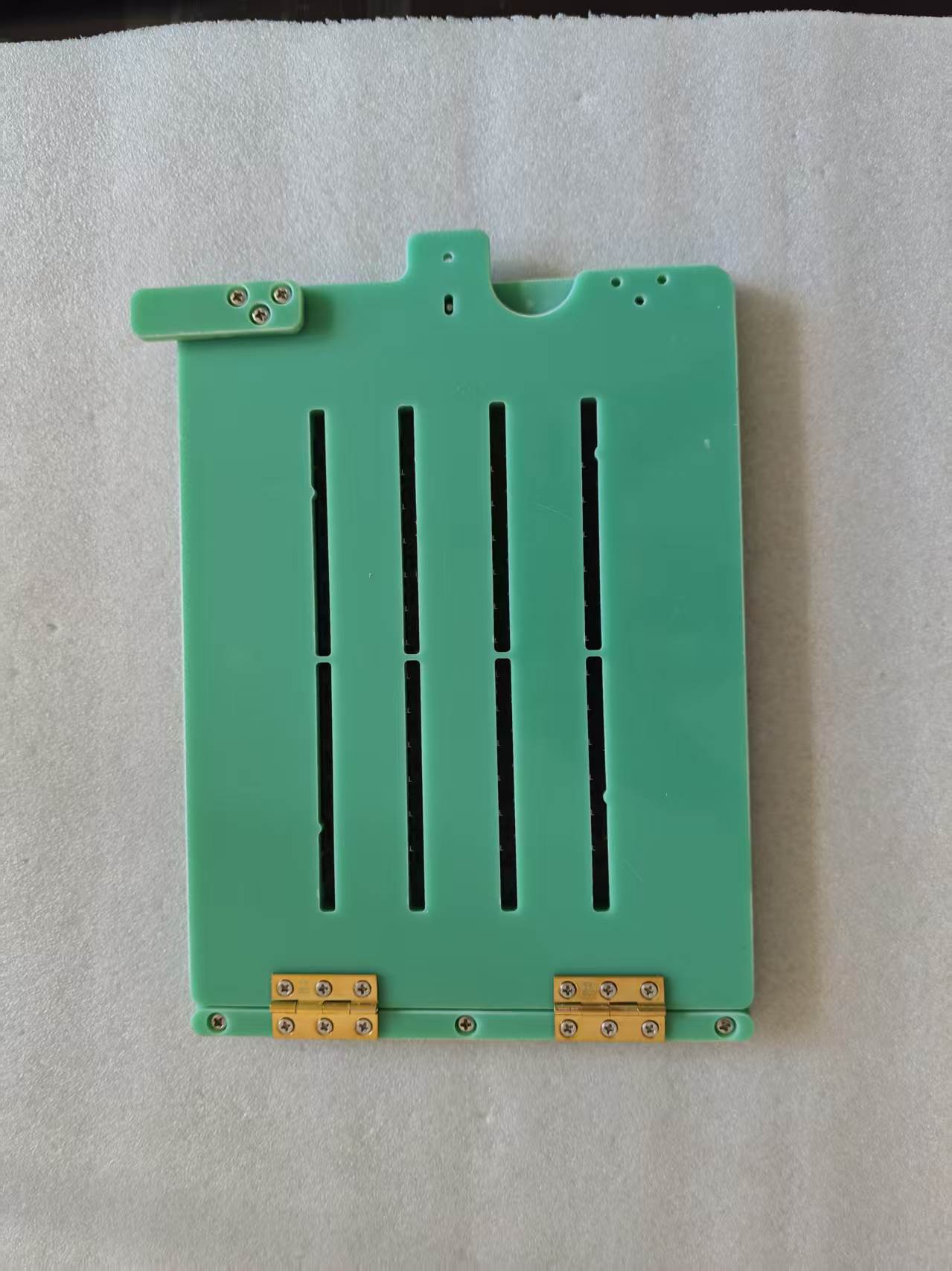
The hinged cover and mechanical stops help the operator repeat the same loading sequence. Brass-colored hinges, screws and machined plates also show how a finished fixture combines tooling material with standard and custom hardware.
Watch the Real Fixture
The video shows the actual fixture structure, opening action, machined slots and installed hardware.
Different Processes Need Different Fixtures
A depaneling fixture is designed around a cutting path. An assembly fixture is designed around component access. An inspection fixture is designed around visibility, and a test fixture around electrical or connector access. That is why the correct first question is not only “What size is the PCB?” but “Which operation must the fixture support?”
Material is part of that decision. For room-temperature positioning, general FR4-type tooling may be considered; sensitive assemblies may require a verified ESD-safe composite; repeated thermal exposure may require a high-temperature tooling grade. Read our PCB Fixture Material Selection Guide for the engineering trade-offs.
Information Required for a Quotation
- Gerber, STEP or CAD file
- PCB or panel dimensions and thickness
- Top and bottom PCBA photographs
- Tooling-hole and keep-out information
- Application and cycle expectations
- Machine model and interface dimensions
- Temperature and ESD requirements
- Required quantity
Frequently Asked Questions
Can one PCB fixture be used for several processes?
Sometimes, but only when support, access, temperature and machine-interface requirements are compatible. Combining processes should be evaluated during design rather than assumed.
Is a PCB router fixture the same as a generic PCB holder?
No. A router fixture must preserve cutter clearance and support the panel against routing forces. A generic holder may locate the board but still interfere with the tool path or allow vibration.
Can Southern Machinery design from photographs only?
Photographs can support a preliminary review, but Gerber, STEP, CAD or a physical sample is recommended for accurate machining and clearance verification.
Need a Custom Fixture for Your PCB?
Send us your Gerber / STEP file, PCB dimensions, PCBA photos and application requirements. Our engineering team can evaluate the PCB, process and machine interface together.
Southern Machinery — Customized SMT & PCBA Tooling Solutions
Visit SMTHELP