A custom PCB fixture is developed by combining PCB data with the real manufacturing operation. A reliable project moves through requirement definition, PCB/PCBA analysis, locating and support design, material selection, CNC machining, mechanical assembly and verification with the actual board.
Explore common PCB fixture applications, including depaneling, assembly, inspection and handling.
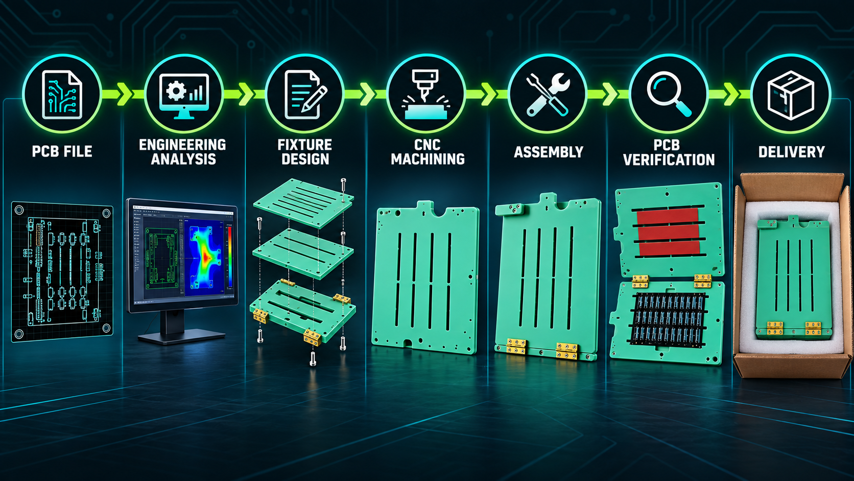
Custom PCB Fixture Design Process at a Glance
PCB File → Engineering Analysis → Fixture Design → CNC Machining → Assembly → PCB Verification → Delivery
Step 1 — Define the Application
Start with the operation, not the plate color or outside size. Is the fixture for router depaneling, assembly, manual insertion, inspection, functional testing, programming, handling or automated equipment?
The answer sets the priorities. A router needs cutting clearance. Assembly needs component access. Testing needs probe and connector access. Automation needs repeatable external datums.
Step 2 — Collect PCB and PCBA Data
The most useful package includes:
- Gerber files and panel drawing
- STEP or other 3D model
- PCB outline, thickness and tooling holes
- Top and bottom assembly drawings
- Maximum component heights
- Keep-out and sensitive-component zones
- Clear top and bottom photographs
- Physical samples when available
3D data helps detect interference, while a physical sample supports final fit verification.
Step 3 — Analyze PCB, Process and Machine Together
The engineer identifies safe support areas, usable locating features and required access. Machine details such as worktable dimensions, conveyor direction, clamp zones, sensors and tool travel must be considered with the board.
This systems view prevents a common failure: a fixture that fits the PCB but does not fit the production process.
Step 4 — Design Positioning and Support
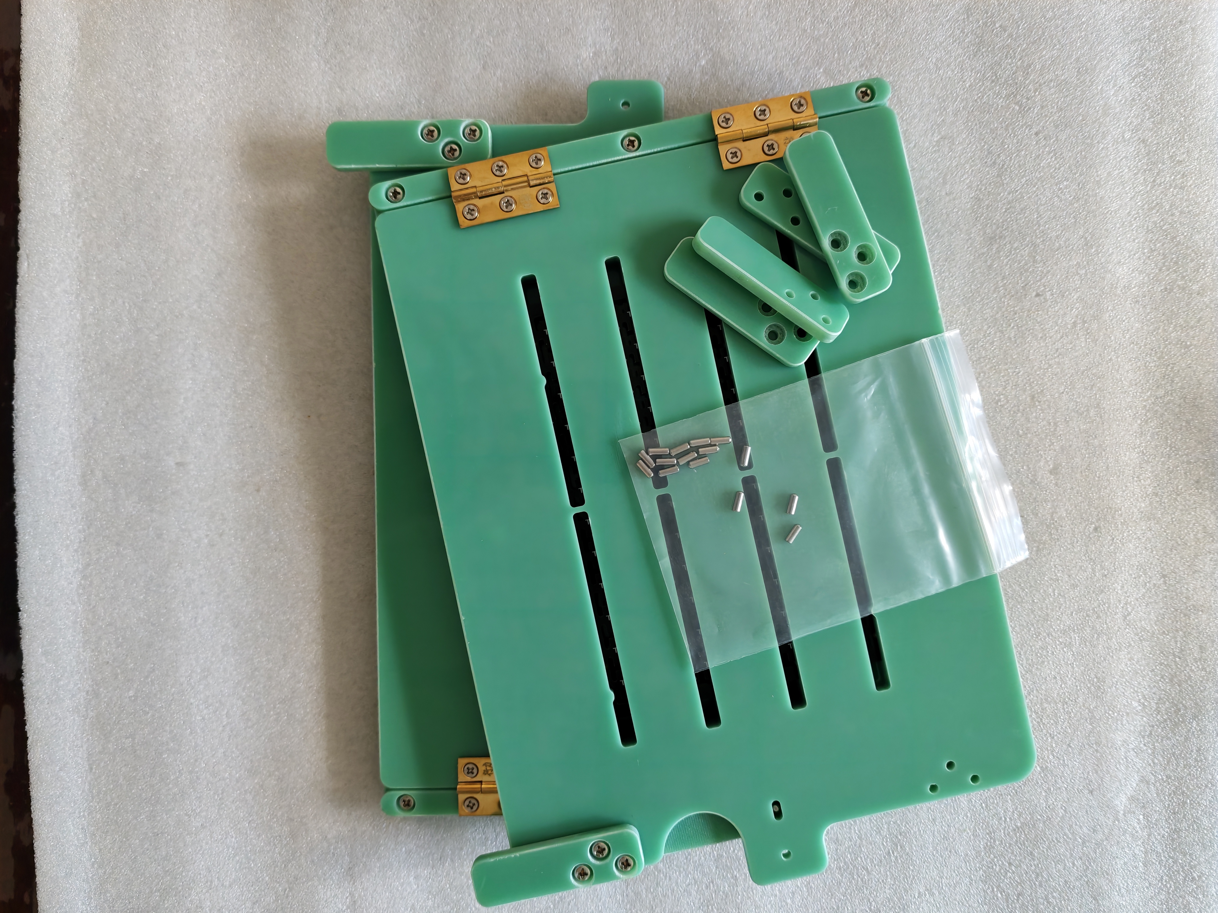
Positioning may use two tooling holes, board edges, a machined pocket, stops, pins, clamps or custom blocks. Support must resist the expected load without contacting components.
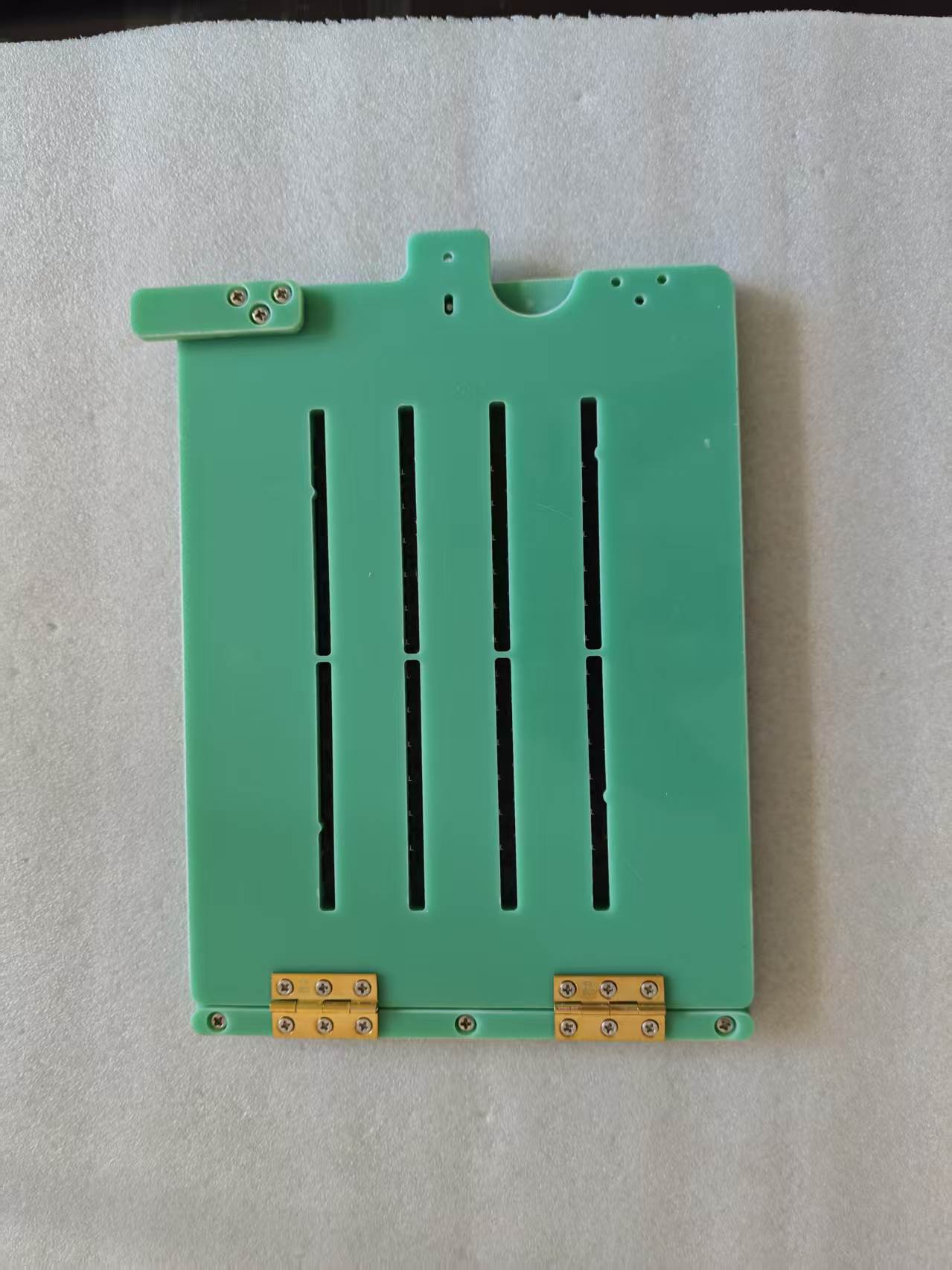
The photographed fixture includes separate blocks and pins, allowing mechanical features to be adapted around the actual PCB. Replaceable parts can also improve maintainability at high-wear locations.
Step 5 — Design Component and Tool Clearance
A populated PCB is three-dimensional. Connectors, capacitors, transformers, IC packages, heat sinks and bottom-side parts require relief. The fixture must also leave space for cutters, cameras, probes, screwdrivers, insertion tools or robot grippers.
Clearance should be intentional: too little risks collision; too much can remove necessary support.
Step 6 — Define Loading, Closing and Locking
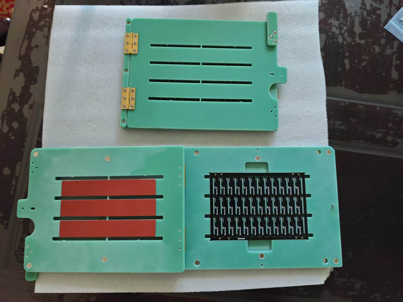
Some fixtures need only a base. Others benefit from a hinged cover, removable insert or dedicated clamp. The operator should be able to load the board in only the correct orientation, close the fixture without hitting components and remove the PCB without excessive force.
Ergonomics matters when the action is repeated hundreds of times per shift.
Step 7 — Select Material and Thickness
Material is finalized after the process is understood. Selection may consider rigidity, ESD behavior, temperature, wear, machinability, weight, cleaning method, expected cycles and cost.
General FR4-type laminate, verified ESD composite and high-temperature tooling grades serve different environments. The exact grade should be documented rather than inferred from color.
Step 8 — CNC Machine the Fixture
Machining may create PCB pockets, slots, locating bores, component reliefs, mounting holes, edge profiles and tool-access openings. Tolerances should be tight where they control location and practical elsewhere.
Long slots in the real fixture provide access and remove material in selected zones while leaving the structure required by the design.
Step 9 — Assemble Mechanical Components
The machined plates are combined with hinges, screws, pins, stops and custom blocks. Fasteners should be secure, moving parts should operate freely and replaceable components should be accessible.
Step 10 — Load the PCB and Verify Fit
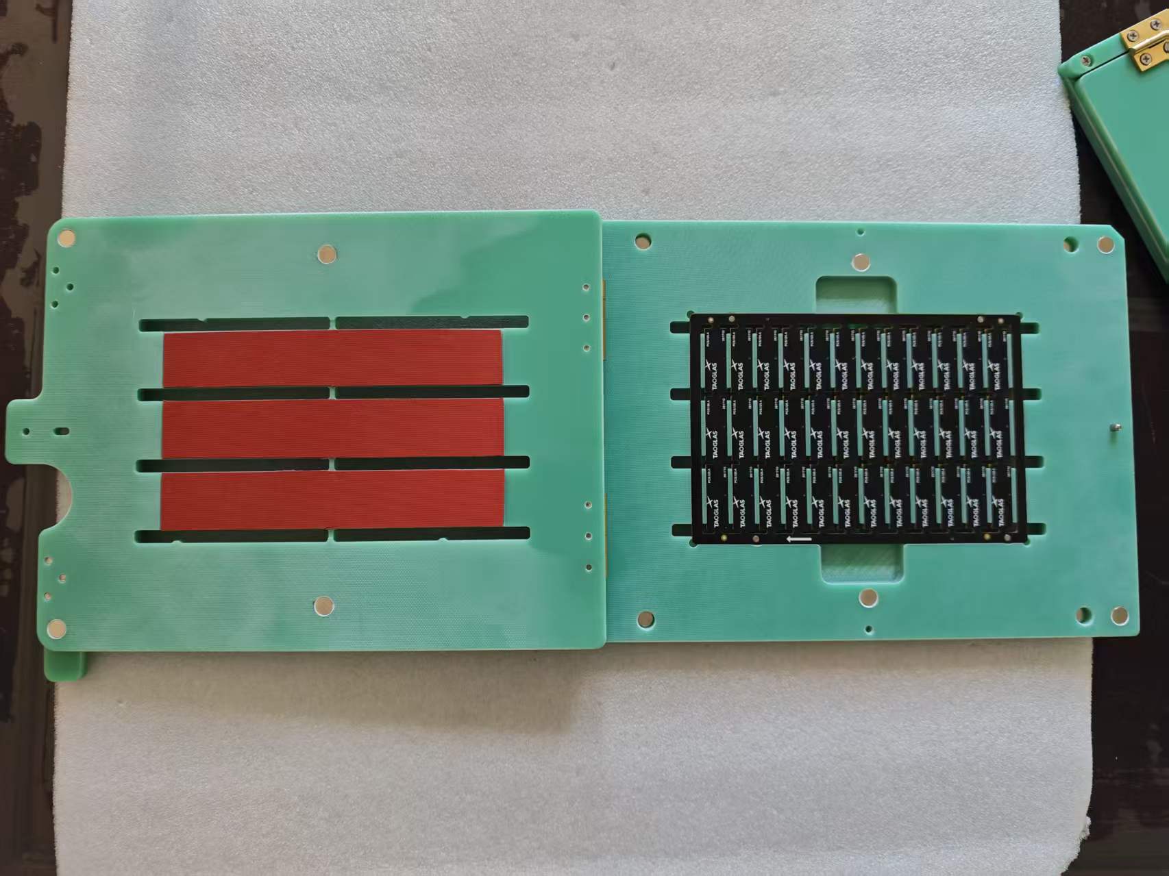
Verification should cover:
- Loading and unloading
- Board orientation and repeatable positioning
- Component clearance
- Opening, closing and locking
- Machine, cutter, camera or probe access
- Interference and flexing
- Trial cycles with actual production conditions
For a router fixture, confirm the complete cutting path. For assembly, confirm every required component position. For test, confirm probe and connector engagement.
Step 11 — Release for Production
After fit and process checks, record the final drawing, material grade, replaceable components and revision. This creates a maintainable production tool rather than an undocumented one-off plate.
Watch the Finished Fixture
The video provides a real-world view of the fixture's size, hinged construction, machined surfaces and hardware.
What Should You Send to the Fixture Supplier?
| Required input | Preferred format |
|---|---|
| PCB geometry | Gerber, CAD or dimensioned drawing |
| Assembly geometry | STEP file and top/bottom photos |
| Application | Written process description or video |
| Machine interface | Model, drawing and work-area dimensions |
| Production conditions | Temperature, ESD, cycle and cleaning requirements |
| Commercial input | Quantity, delivery target and validation expectation |
Frequently Asked Questions
Can fixture design start without a STEP file?
Yes. Gerber data, dimensioned drawings, photographs and a physical sample can support development, although complete 3D data reduces clearance uncertainty.
Why is a physical PCB sample useful?
It allows direct checks of fit, loading force, component clearance and manufacturing tolerance before release.
How is a custom fixture different from a universal holder?
A universal holder adapts its structure to many boards. A custom fixture is designed around one PCB or product family and its specific process, so locating, support and access can be optimized.
What information most often prevents redesign?
Accurate bottom-side component data, the real machine interface, the full tool path and clearly stated temperature or ESD requirements.
Need a Custom Fixture for Your PCB?
Send us your Gerber / STEP file, PCB dimensions, PCBA photos and application requirements. Our engineering team can evaluate your PCB and develop a fixture around the actual production process.
Southern Machinery — Customized SMT & PCBA Tooling Solutions
Visit SMTHELP